MAPPING WITHOUT GROUND CONTROL POINTS: DOES IT WORK?
BACKGROUND
The economic advantages of Structure from Motion (SfM) mapping without any ground control points have motivated us to investigate an approach that relies on accurate camera exposure positions instead of Ground Control Points (GCP) for geo-referencing purposes.
Our test bed is a 230m x 230m section of a parking lot of the local community college. We chose this site because it has many permanent road markings which can be used as aerial targets and check points over a period of time without the need for target maintenance. Hence we had to invest once only in the survey of some 120 permanently marked control points distributed more or less evenly across the test bed. The check points were surveyed by means of kinematic post-processed dual frequency GPS with multiple occupations to eliminate centering errors. Only fixed ambiguity solutions were accepted in the final calculation of check point coordinates in the NAD83 UTM 17 N coordinate system. The accuracy of the control point coordinates is assumed to be better than 2cm. The parking lot is practically vacant over the summer break and during weekends, thus allowing us ample and convenient access for experimentation. Figure 1 below shows the test bed and the available control points.
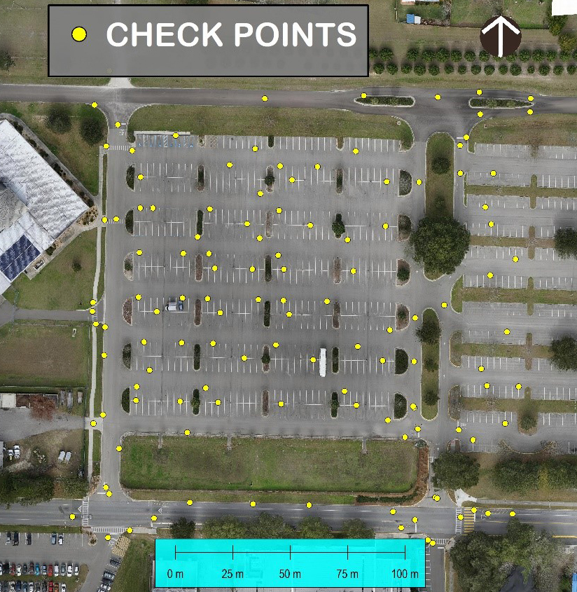
Figure 1: Test Bed with surveyed Check Points
ESTABLSIHING A BENCH MARK DATA SET WITH CONVENTIONAL GROUND CONTROLLED SfM MAPPING
To establish a general estimate of the accuracy that can be achieved in the conventional SfM approach with the use of 12 GCPs selected from the set of available control points, we used a Sony a6000 camera with a 16mm lens to make a map. Using the remaining 110 control points as Check Points (CPs) we could then test the accuracy of the map by comparing the CP coordinates with corresponding map coordinates. This map, as well as the horizontal differences between CP coordinates and corresponding map coordinates is shown in Figure 2 below. Note that for illustration purposes the errors were scaled up by a factor of 1000.
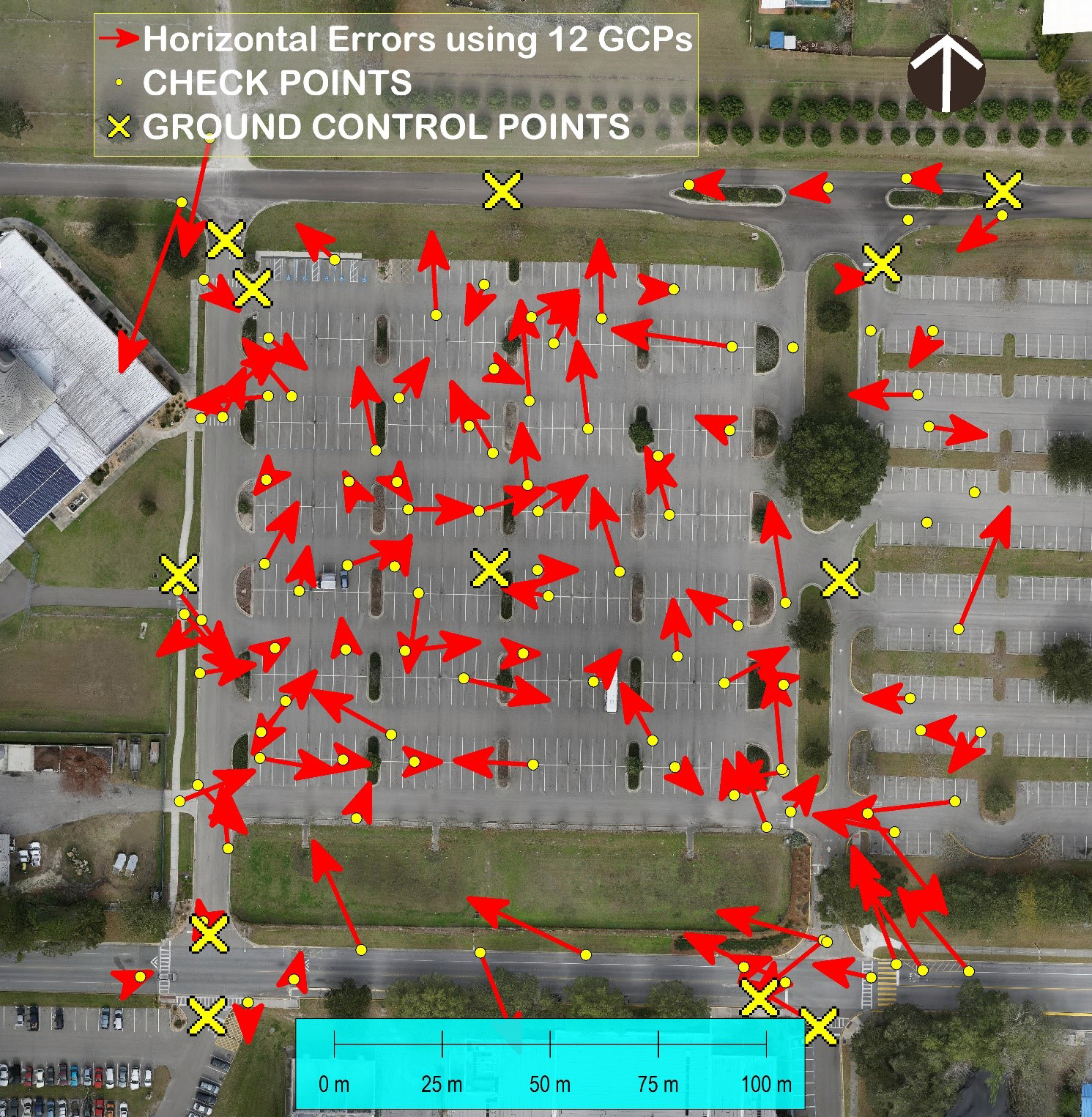
Figure 2: Horizontal Errors (scaled by 1000) resulting from the use of 12 GCPs.
Using a method described in the American Society for Photogrammetry and Remote Sensing (ASPRS) Manual for Photogrammetry and Remote Sensing (4th Edition) for the testing of the geometric quality of raster maps we calculated at 95% confidence level the following accuracy estimates:
Horizontal (“approx. circular Error”): 0.028m (0.092’) Vertical: 0.038m (0.125’)
These values correspond to 2.5 (horizontal) and 3.2 (vertical) respectively of the GSD of the original aerial imagery.
FIRST MAP WITHOUT GROUND CONTROL
We used an Olympus PEN-EP2 camera, a 14mm pancake lens from Panasonic, Photoscan Professional, the well-known SfM program from Agisoft, and our own V-Map dual frequency GPS system mounted on a small quad copter to make a map without using GCPs. A specially designed cable was used to connect the hot-shoe port of the camera to the event marker port of the drone mounted V-Map unit. Camera management was independently done by the auto pilot, in this case an APM 2.6 from 3D Robotics. The reference station for the airborne survey was a second V-Map unit mounted over a Control Point with known NAD83 UTM 17N coordinates. The horizontal errors resulting from a comparison between the SfM derived map coordinates and the corresponding GPS derived coordinates of some 120 Check Points are shown in Figure 3 below.
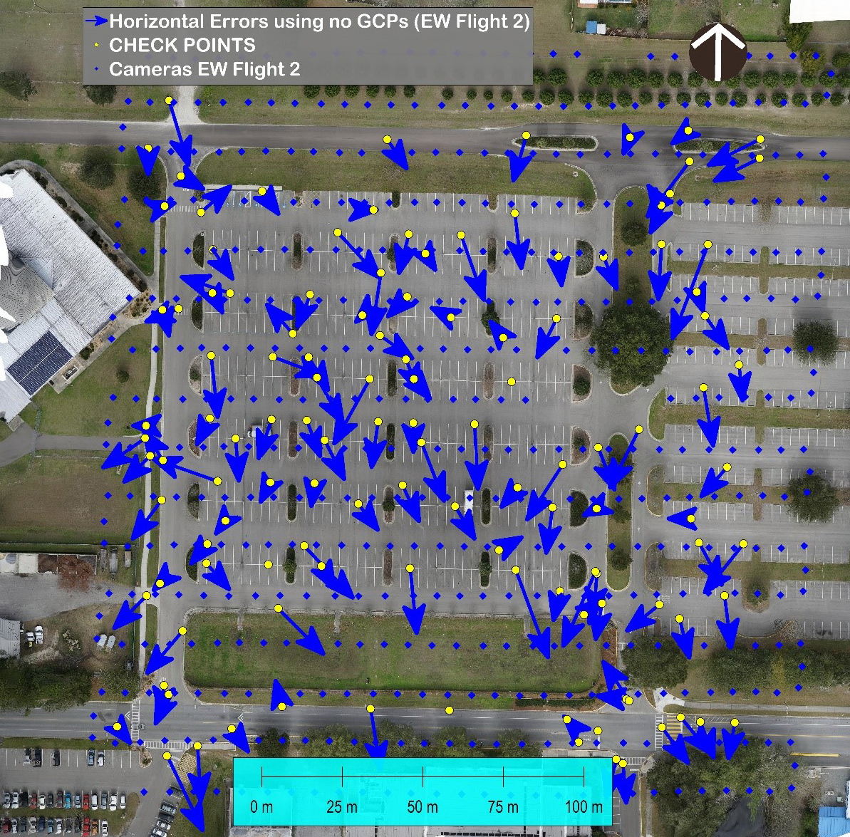
Figure 3: Horizontal errors (scaled by 1000) of first map
The 95% confidence level accuracy estimates for this map were as follows:
Horizontal (“approx. circular Error”): 0.032m (0.105’) Vertical (after removal of a 0.041m bias): 0.038m (0.125’)
Further error statistics are shown in Table 1 below.
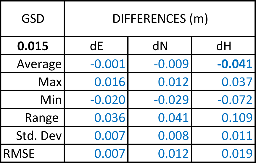
Table 1: Error statistics for first map produced without GCP
Except for the bias of 0.041m in the vertical, the above results indicate no significant degradation of accuracy when compared to the conventional GCP approach. In terms of GSD (14.7mm) dimensions the horizontal and vertical error estimates amount to 2.1 and 2.5 pixels respectively.
SECOND MAP WITHOUT GROUND CONTROL
To test whether these results are repeatable we acquired a second, independent set of aerial images, this time orienting the flight lines in a N-S direction instead of E-W as was done for the first map.
The 95% confidence level accuracy estimates for this map were as follows:
Horizontal (“approx. circular Error”): 0.025m (0.082’) Vertical (after removal of a 0.014m bias: 0.041m (0.135’)
Further error statistics for this map are shown in Table 2 below.
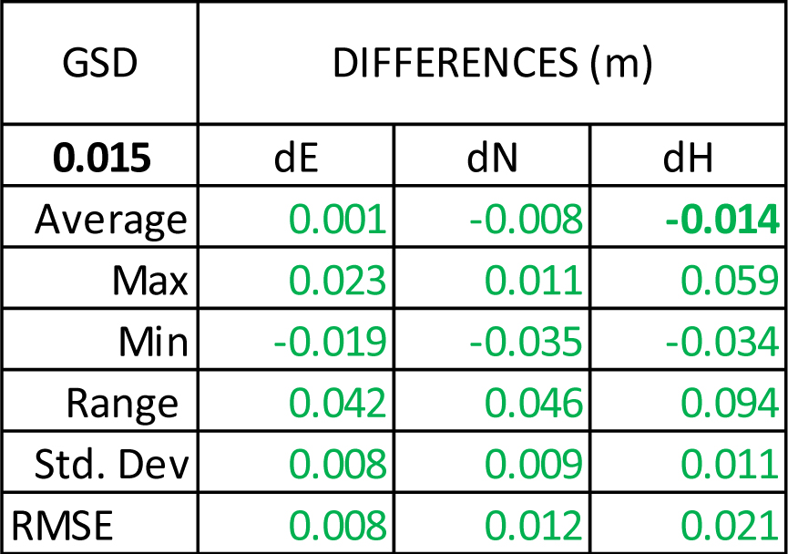
Table 2: Error statistics for second map produced without GCP.
In this case the results indicate no significant degradation of accuracy when compared to the conventional GCP approach. In terms of GSD (14.7mm) dimensions the horizontal and vertical error estimates amount to 1.7 and 2.8 pixels respectively.
The horizontal errors resulting from a comparison between the SfM derived map coordinates of our second map and the corresponding GPS derived coordinates of some 120 Check Points are shown in Figure 4 below.
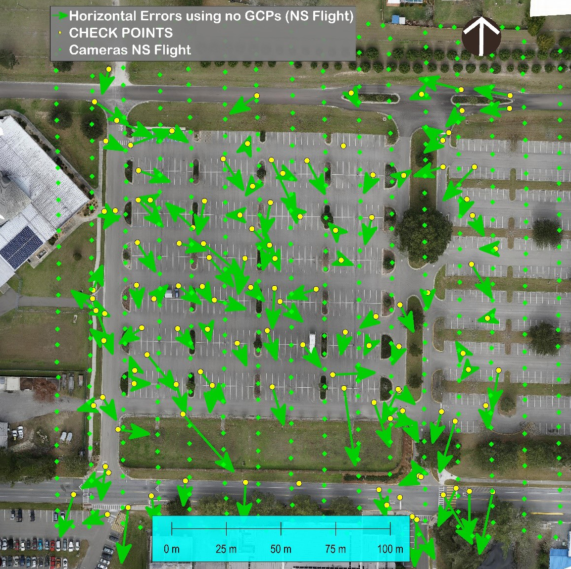
Figure 4: Horizontal errors (scaled by 1000) of second map
SUMMARY AND CONCLUSIONS.
A combination of the errors for both the first and the second map is shown in Figure 5 below.
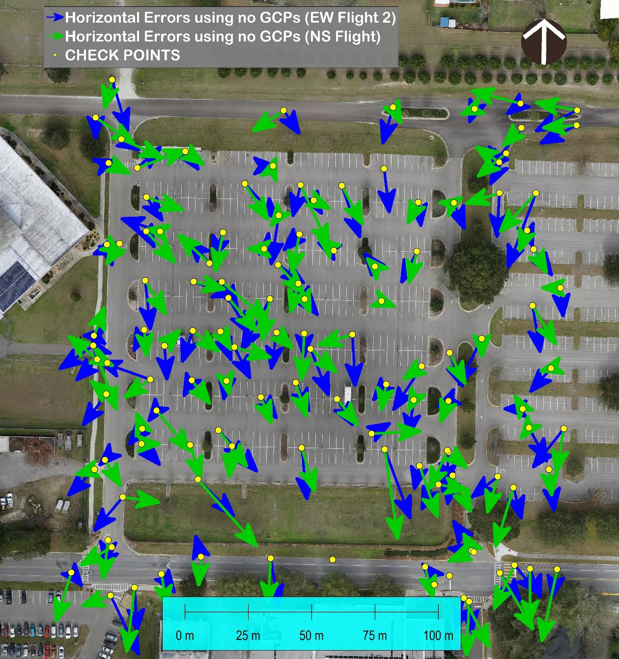
Figure 5: Horizontal errors (scaled by 1000) of both the first and second map
Note that there is some apparent correlation between the two error sets. This may in fact indicate that the GPS survey was not sufficiently accurate to serve as a bench mark for SfM accuracy estimating or that the targets of the CPs have deteriorated in the time span between GPS survey (January 2015) and date of image acquisition (August 2015).
The above results indicate that in SfM mapping the use of Camera Exposure Positions (CEPs) instead of GCPs does not significantly reduce the accuracy. The vertical bias of the first flight needs further investigation. It can however be mitigated by using one known elevation in the object space for a systematic correction of the elevations. Further flights over the same and other test beds will be conducted to firm up the above conclusions.
Download our White Paper by clicking here: MAPPING WITHOUT GROUND CONTROL POINTS